Email us
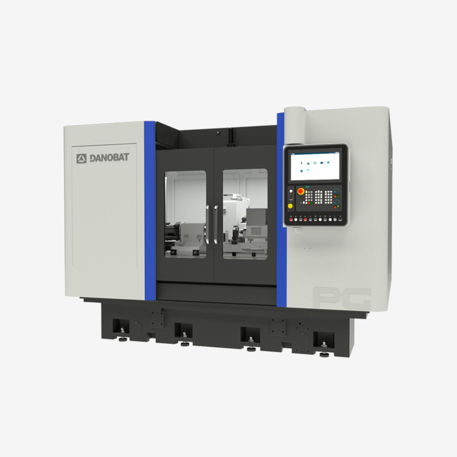
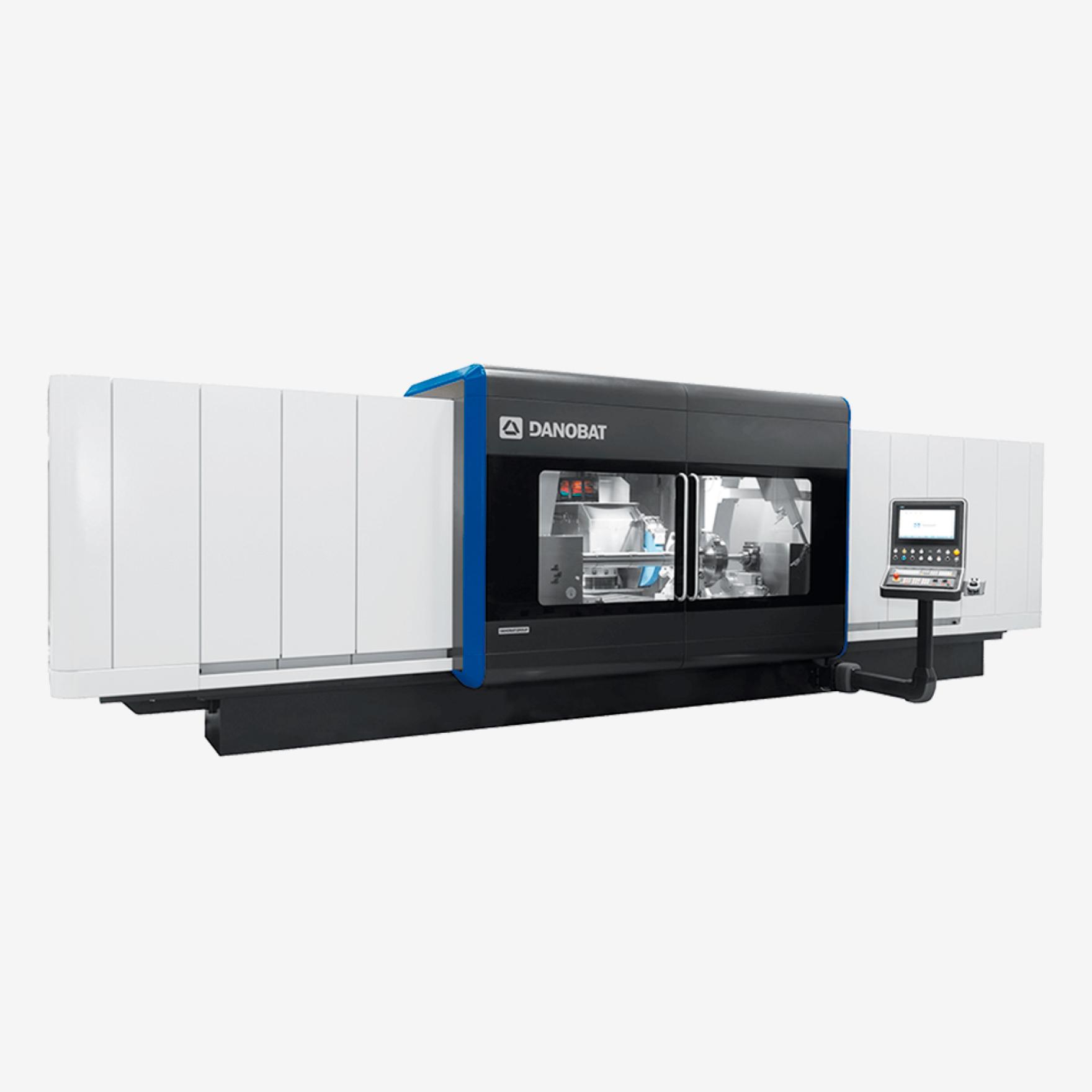
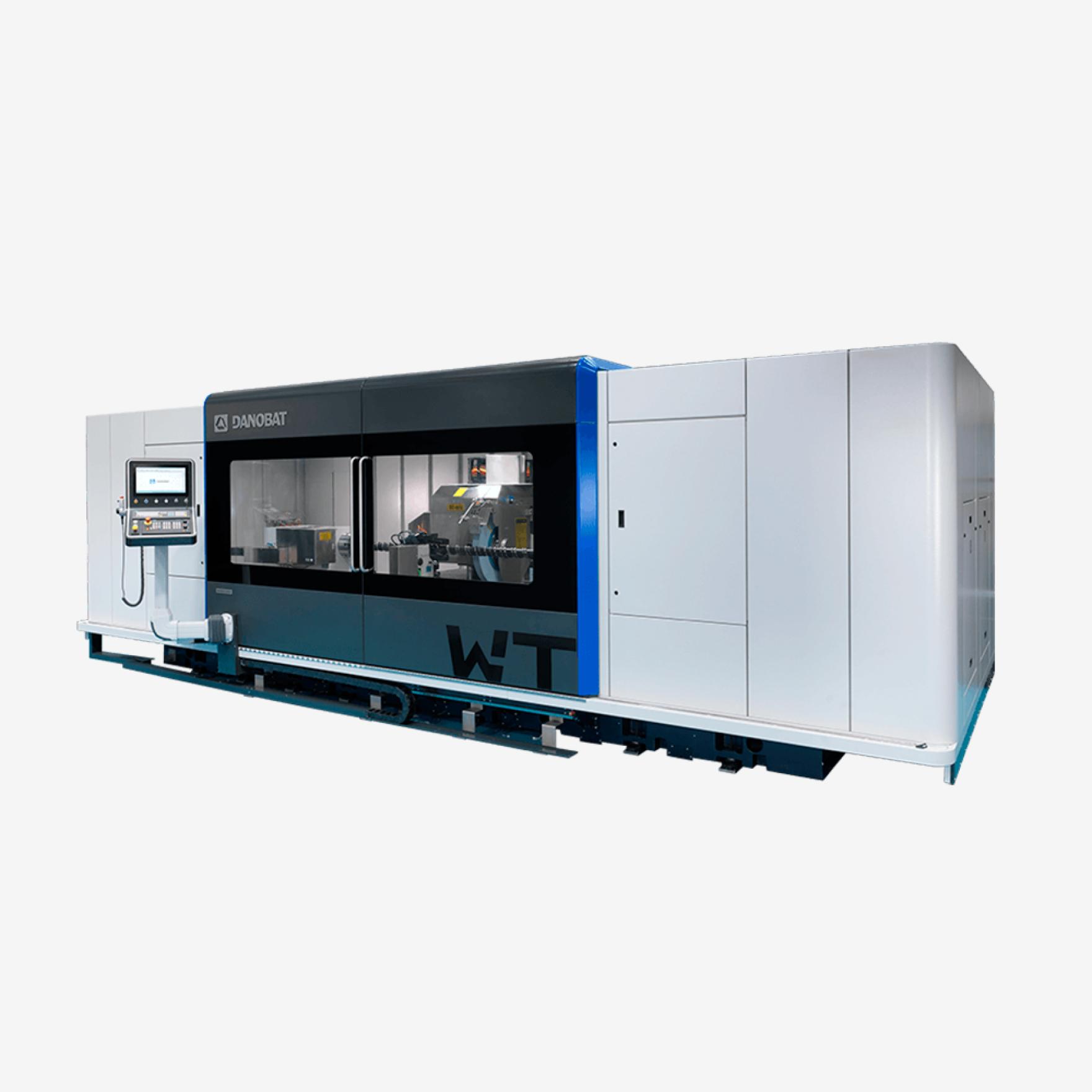
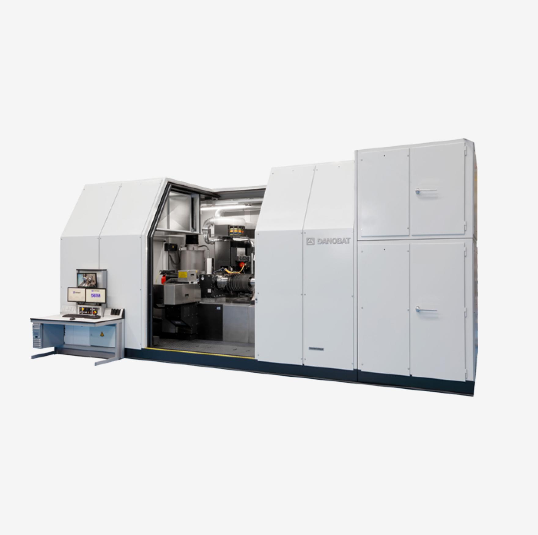
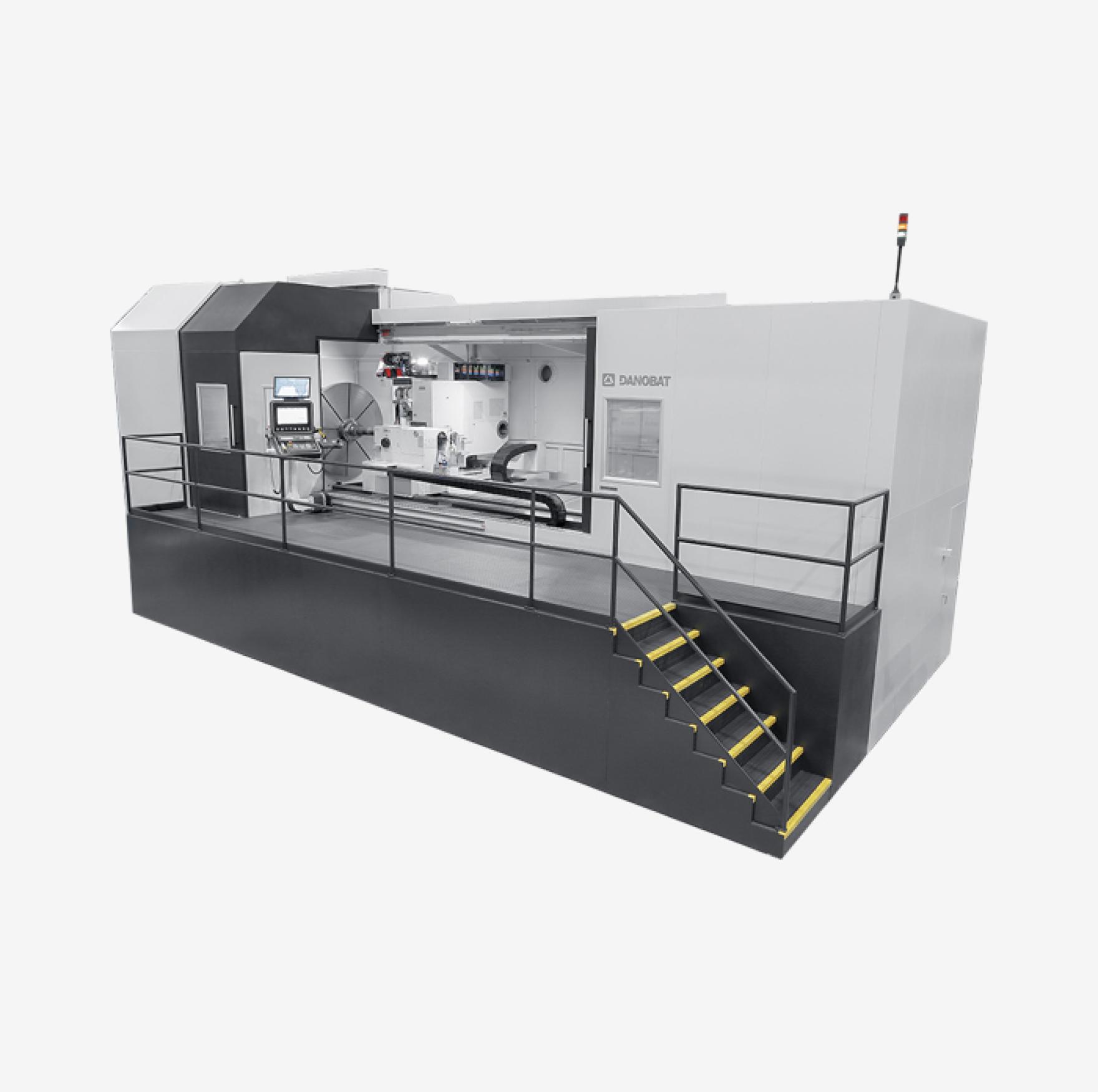
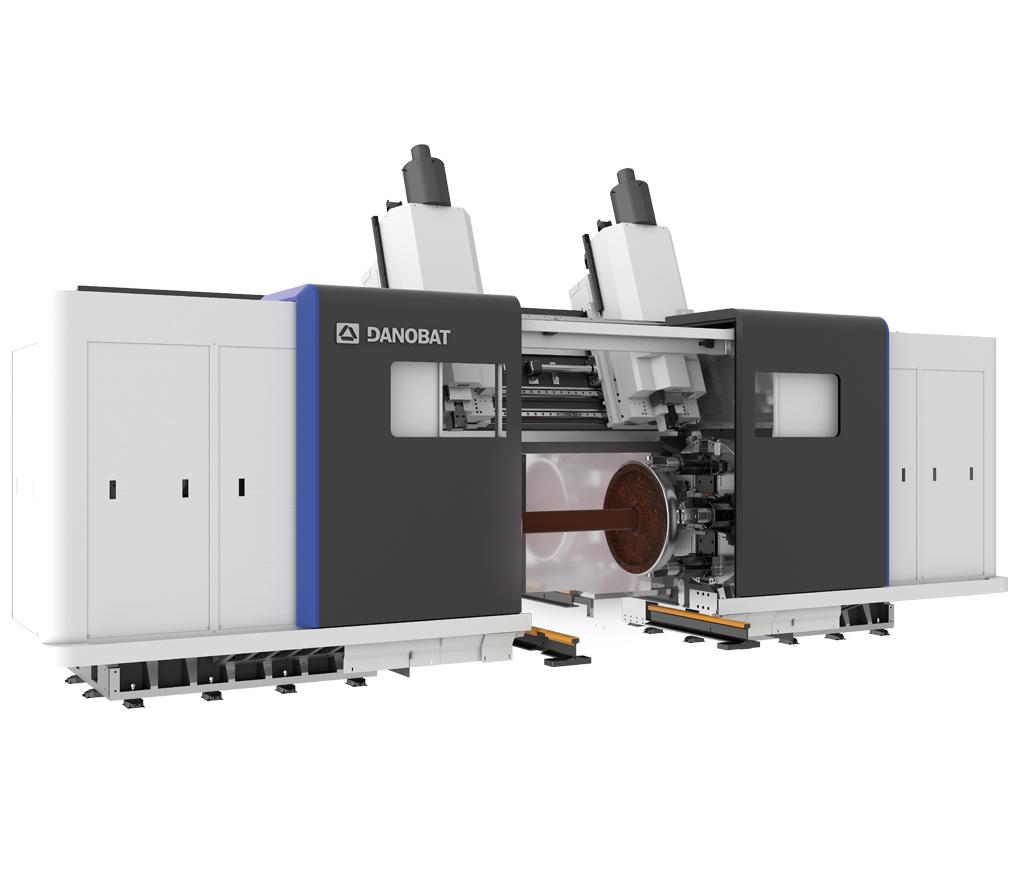
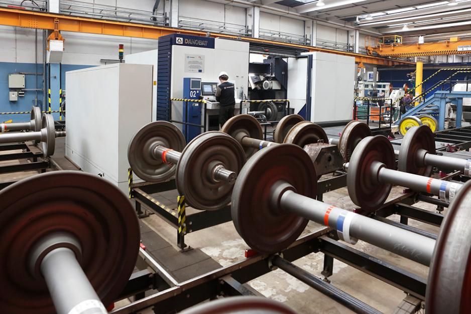
PORTAL LATHE FOR WHEELSET REPROFILING AND BRAKE DISC TURNING
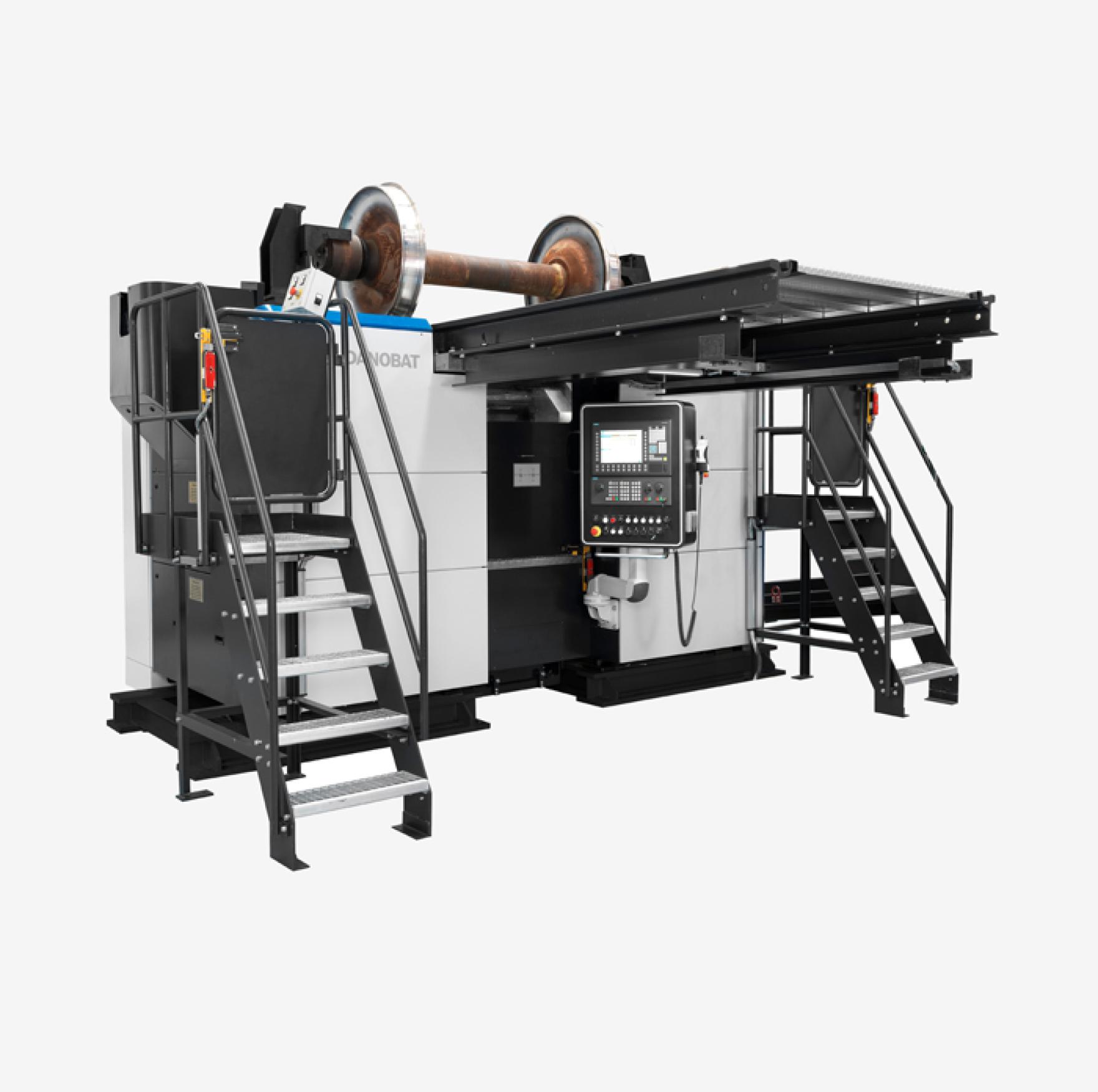
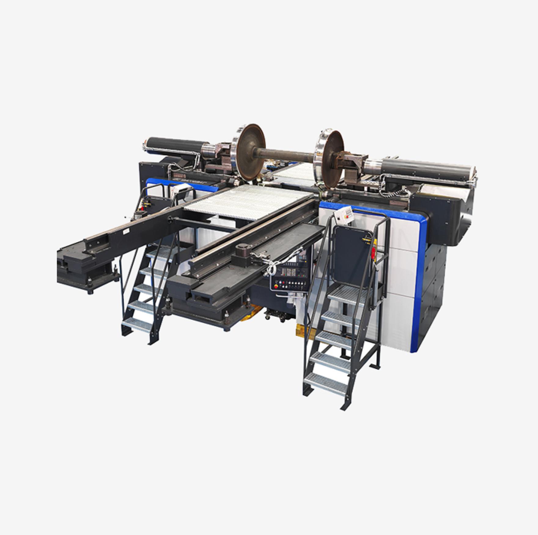
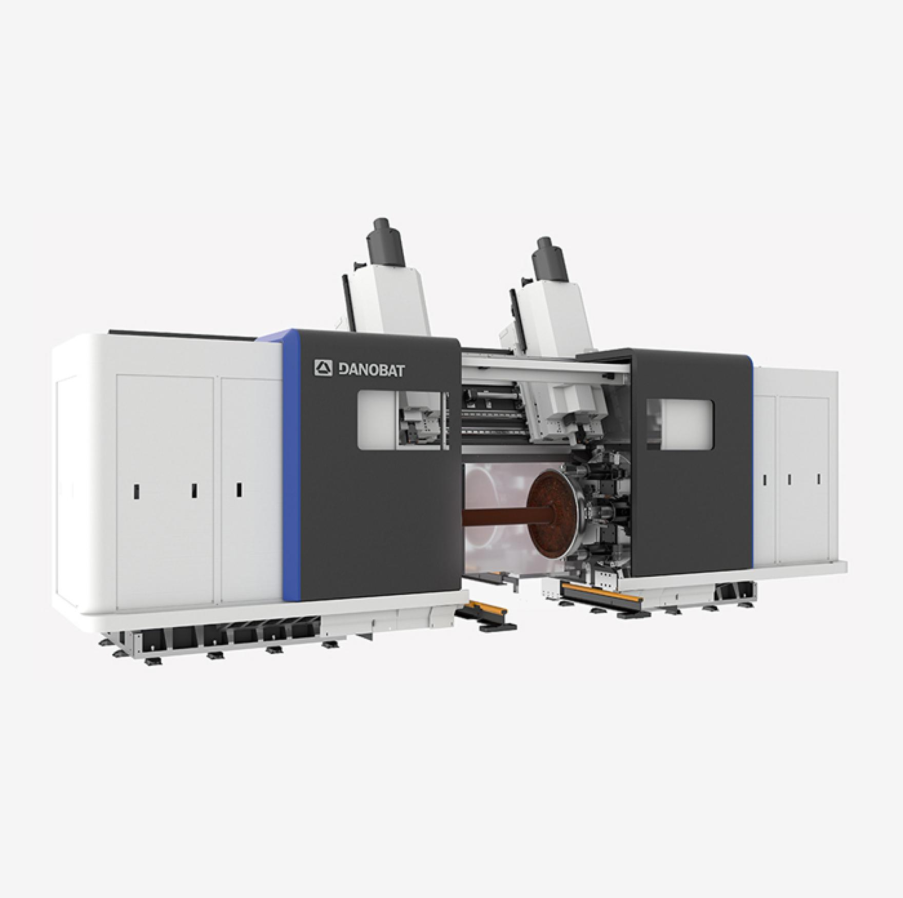
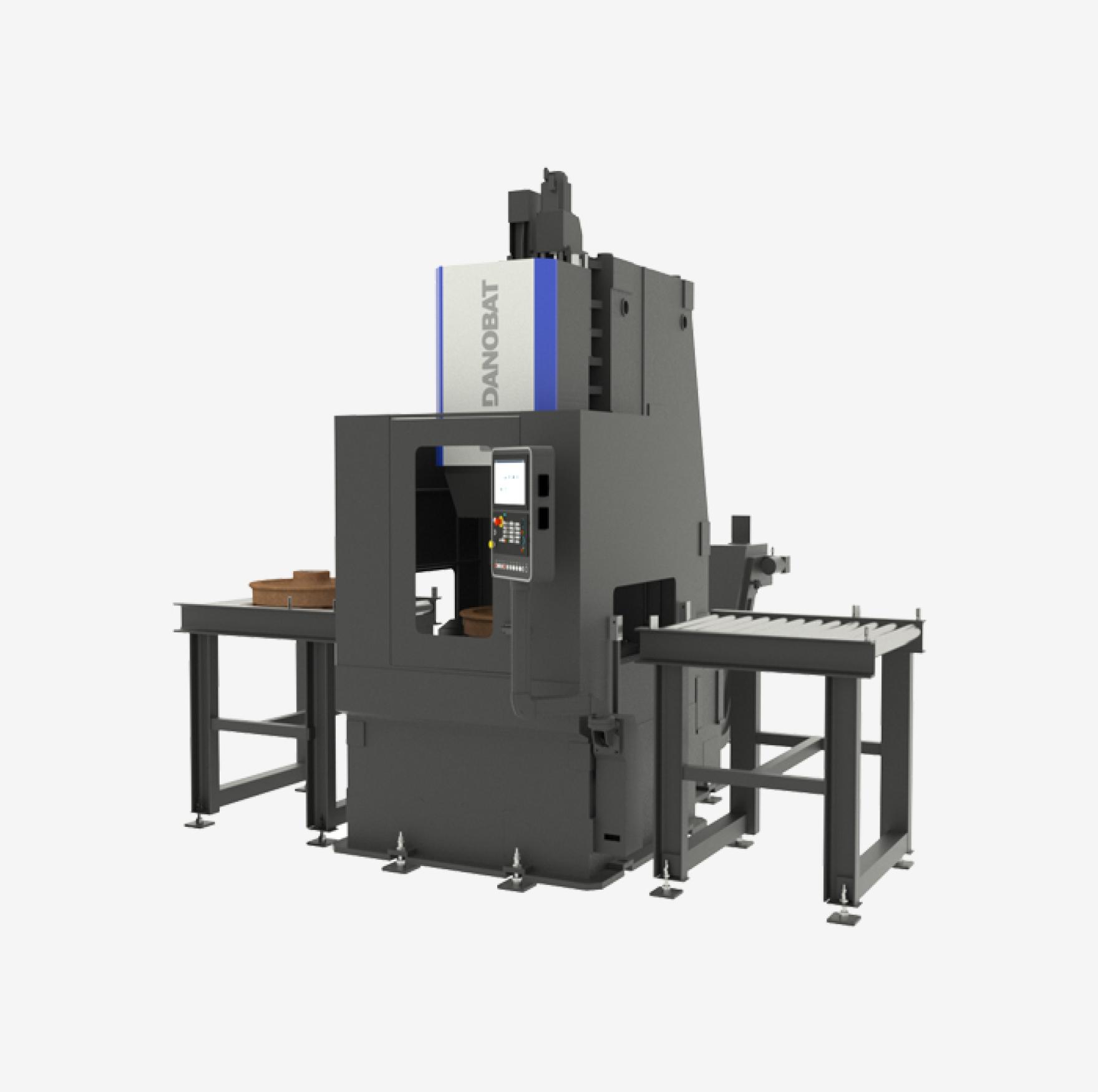
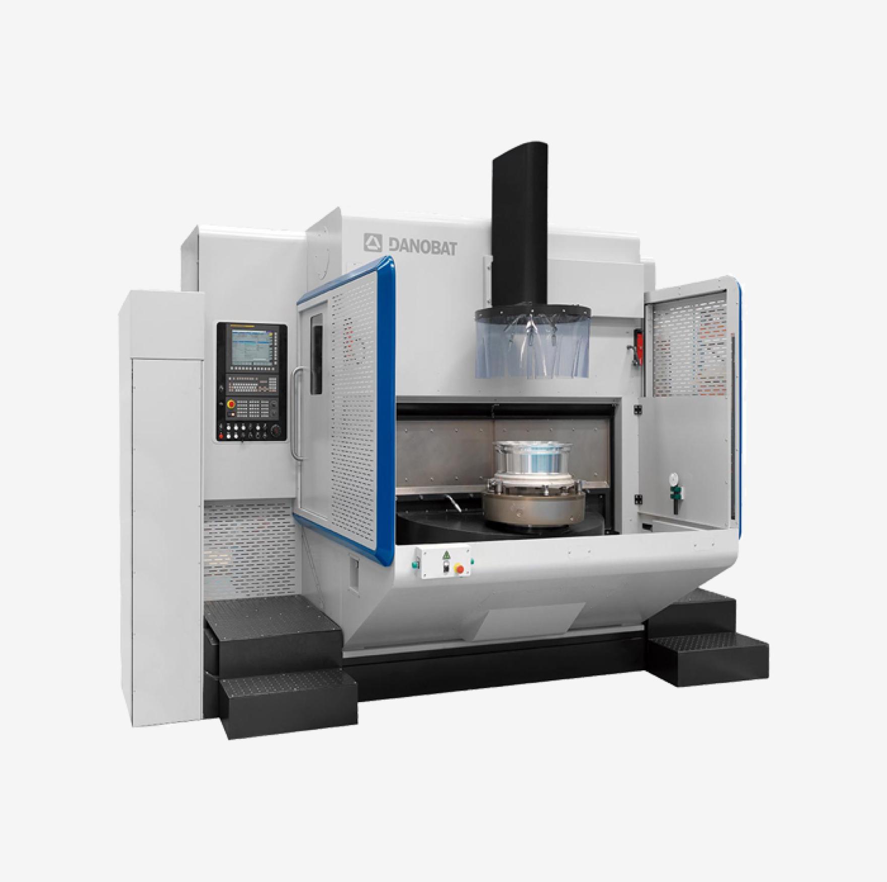
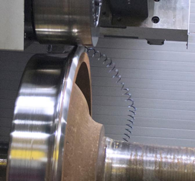
Specifically designed and manufactured for high accuracy railway wheel reprofiling, plus brake disc machining.
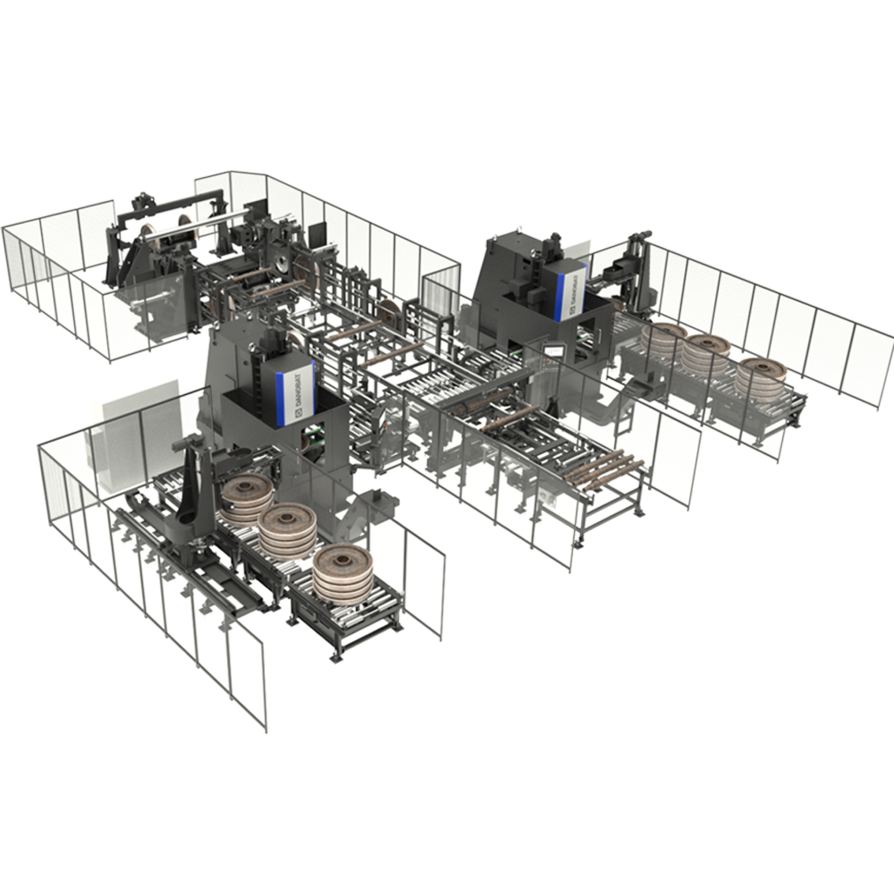
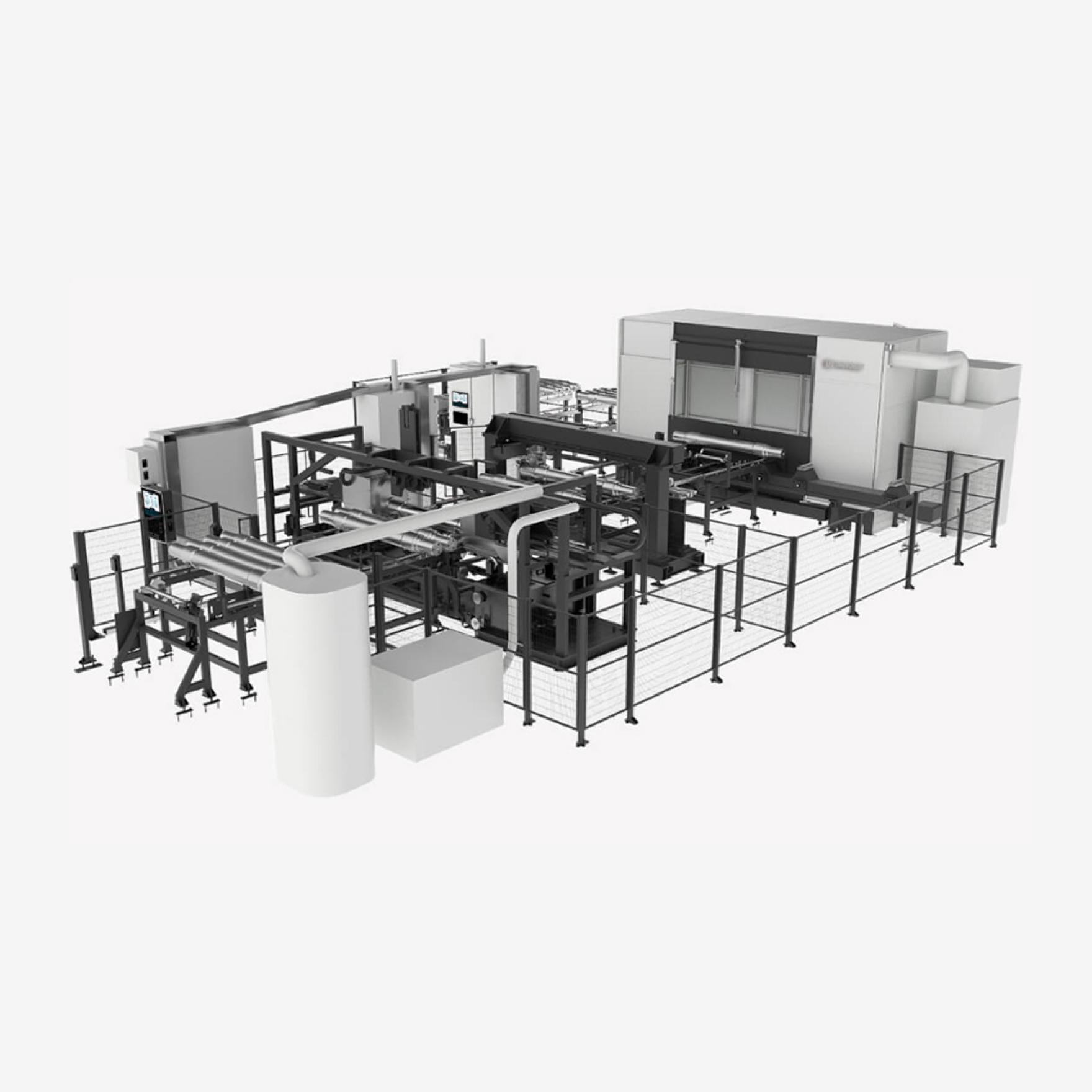
It features the latest smart manufacturing technology to maximize your throughput.
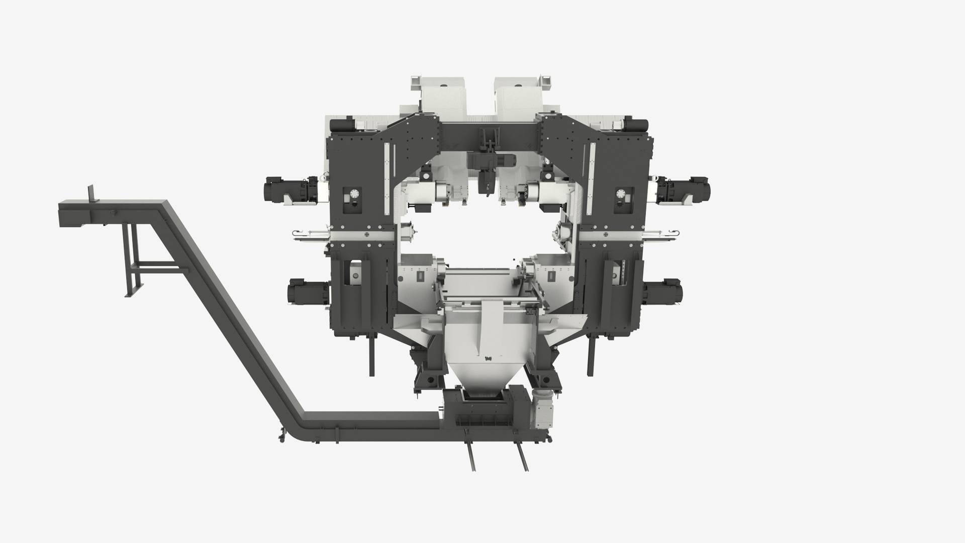
Full cast iron machine structure
Best performance against temperature variations. Guarantees machine stability and rigidity.
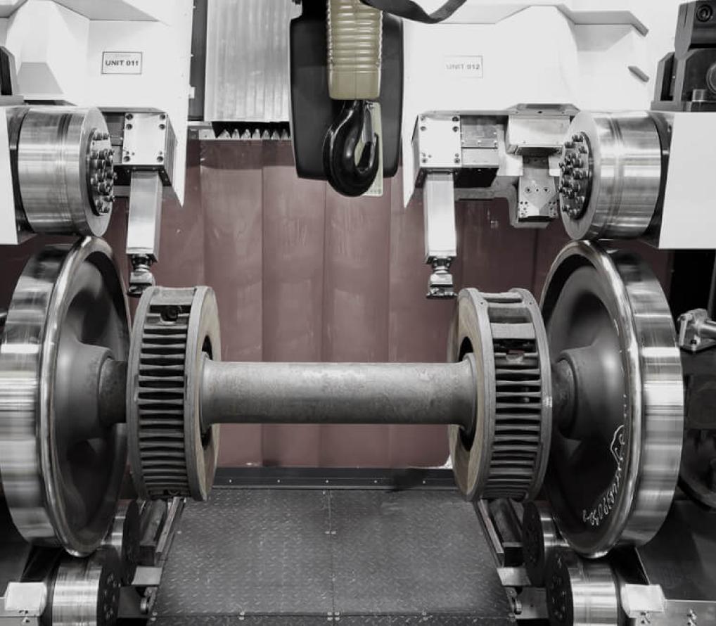
Friction rollers
- 6 friction rollers (3 on each wheel), with wheel flange contact
- Lower rollers lift the wheelset up to the tailstock height
- Pressure automatically adjusted to suit the cutting conditions
Tailstocks
Two tailstocks are hydraulically actuated and include a mechanical blocking system for the best performance.
X and Z carriages
- Three linear guideways (Z) with recirculating roller box bearings, actuated by servomotor and gearbox
- Houses the cutting tools, measuring system, and video-cameras
- Suction nozzles that remove chips, fumes, and mist
Wheel measuring system
Mounted on retractable support, protected from chips or impacts. It measures:
- Initial measurement
- Final measurement
- Option to add brake disc wear measurement
Swarf treatment (crusher and conveyor)
Provides efficient chip removal for proper machine operation.
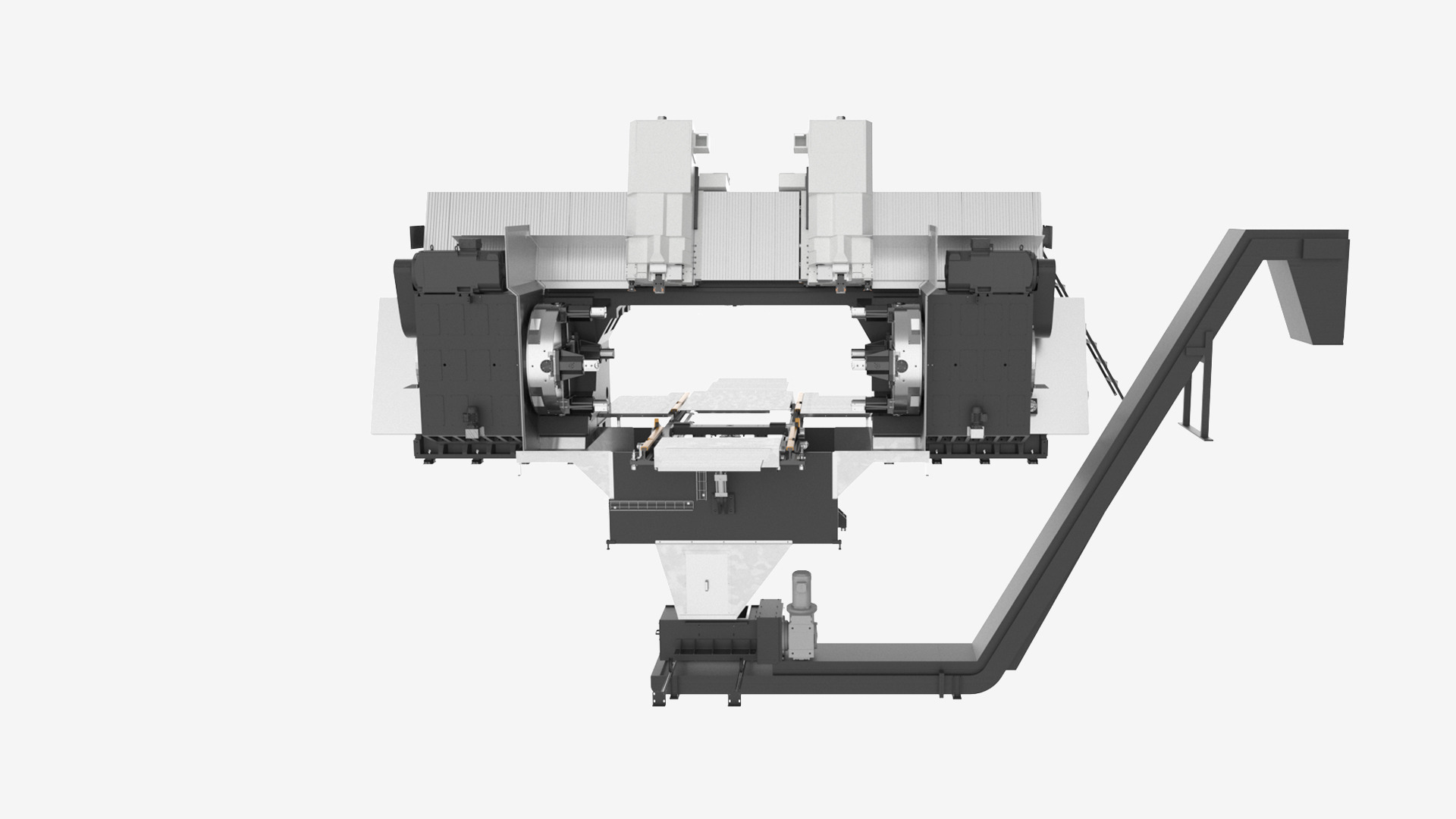
Full cast iron machine structure
Best performance against temperature variations. Guarantees machine stability and rigidity.
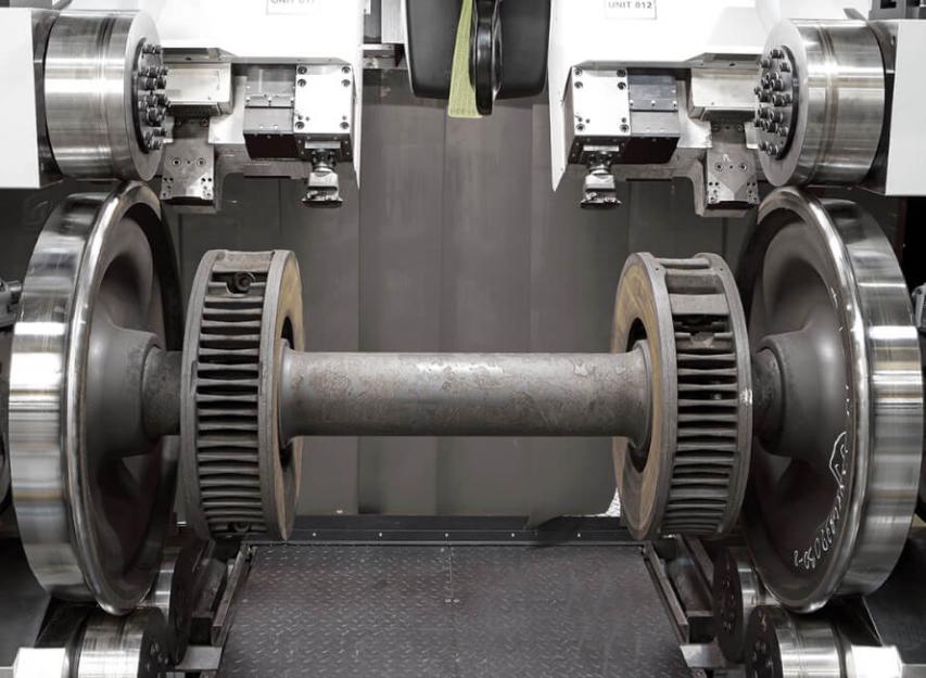
Clamping chucks
- Spindle motor power = 2 x 110 hp (2 x 81 kW)
- Transmission via belt pulley and gearboxes
- The 4 axial clamping jaws are located on both heads
- Roller bearings designed for high loads, adequately sealed and lubricated
Center points
Both centers (hydraulically actuated) guarantee a fixed and repetitive wheelset alignment.
A hydraulic clamping bush locks the center, guaranteeing the correct position.
X and Z cross slides
- The Z axis rides on 3 INA RUE-65 linear guides, providing great rigidity and precision
- Hardened slideways guide the X axis
- The X and Z axes are driven by an Ø3.14" (80 mm) ball screw
Wheel measuring system
Mounted on a retractable support, protected from chips or impacts. It measures:
- Initial measurement
- Final measurement
- Option to add brake discs´ wear measurement
Swarf treatment (crusher and conveyor)
Provides efficient chip removal for proper machine operation.
| DPL | DPL-J | ||
|---|---|---|---|
| Track gauge | mm | 1000/1676 | 1000/1676 |
| Min. / max. wheel diameter | mm | 640/1400 | 640/1400 |
| Min. / max. brake disc diameter | mm | 300/1100 | 300/1100 |
| Drive type | - | Friction rollers | Clamping chuck + Jaws |
| Max. chip section per tool post | mm2 | 18 | 35 |
| Wheel Ø difference | mm | < 0,15 | < 0,15 |
| Wheel circularity – Radial runout | mm | < 0,1 | < 0,1 |
| Lateral wobble of the rim of the wheel – Axial runout | mm | < 0,2 | < 0,2 |
| Wheel profile geometry | mm | < 0,2 | < 0,2 |
| Surface roughness | µm | Ra <6,3 | Ra <6,3 |
| DPL | DPL-J | ||
|---|---|---|---|
| Track gauge | in | 39.4/66 | 39.4/66 |
| Min. / max. wheel diameter | in | 25/55 | 25/55 |
| Min. / max. brake disc diameter | in | 11.8/43.3 | 11.8/43.3 |
| Drive type | - | Friction rollers | Clamping chuck + Jaws |
| Max. chip section per tool post | in2 | 0.028 | 0.05 |
| Wheel Ø difference | in | ≤ 0.006 | ≤ 0.006 |
| Wheel circularity – Radial runout | in | ≤ 0.0039 | ≤ 0.0039 |
| Lateral wobble of the rim of the wheel – Axial runout | in | ≤ 0.0079 | ≤ 0.0079 |
| Wheel profile geometry | in | ≤ 0.0079 | ≤ 0.0079 |
| Surface roughness | µin | Ra <0.24 | Ra <0.24 |
Wheelset
- Yearly preventive maintenance, calibration, and customized plans managed by a seasoned team
- We are prepared to assist you remotely. We respond and manage your request worldwide
